I’ve had never really come into contact with embedded programming, working mostly in python or C#, until a friend of mine asked me for some help with programming a simple controller for RGB strips using Arduino Nanos.
We'd, of course, fail spectacularly.
Not only did our hardware not work quite like intended and a few Nanos died in the process(but that’s a story for another time), but I actually learned a lot from this and similar projects.
And I want to tell you some of my mistakes, what I learned by making them and how to prevent them.
Understanding pinouts
Let’s start with something that is a little bit hard to read if you don't know what you are doing: pinouts.
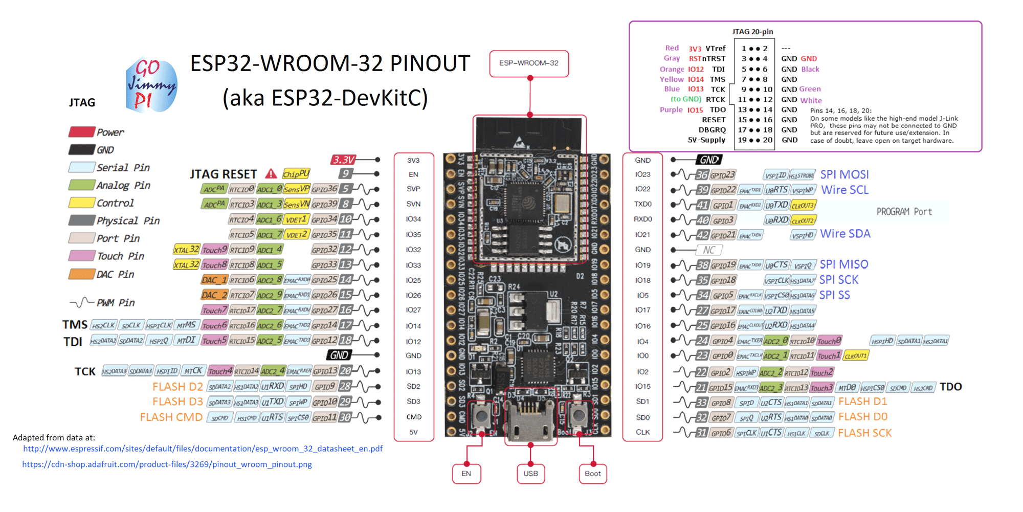
Let me show you how to use them by taking a look at the pinout above and help you to understand some of the more interesting types of pins there are and from which ones you should stay away.
Some additional stuff to look out for
First of all, and this is especially true for the esp32 and its variants, there are a lot of similar pinouts for nearly the same board. Doing the extra step and verifying that you are using the right pinout is crucial.. unless you like the smell of burned electronics.
And while you're at it, try looking up the name of your actual board and research the pin definition of the platform/firmware you are using because it may contain some useful pieces of information about the pins included.
This is quite important as the pinout itself may not contain all the information needed to work with a specific board, for example the limitations some of the pins may have.
In my case, the pins I wanted to use were input only.. good luck trying to control a mosfet with those.
Types of pins and how to use them
Let's return to the topic at hand about what types of pins there are and when and how one should use them.
The most basic pins are digital pins, they can only either be on or off. You would, for example, use them to check if a button is pressed. Or if you use them as output, turning a led on or off.
But if you need finer control you have to use an analog pin. By utilizing a analog to digital converter(ADC) they are able to read analog signals. But their accuracy is somewhat limited by their resolution, the esp32, for example, is limited to 4096 different levels(12 bit).
And while those pins cannot output a true analog signal, they can use a technique called PWM to approximate one by only switching the signal on for some time.
Analog pins are usually used to get accurate data from sensors(a hall sensor for example) or to dim leds(rgb anyone?).
Then there are communication pins that allow the device to communicate. There are several interfaces to choose from, for example UART for direct communication, I2C for on-board internal communication and SPI and 1-Wire for inter device communication, just to name a few.
Beware of pins that are used by the device itself or are used to control the device, they may exhibit unexpected behavior(send signals in regular intervals or in an event for example) and using them could fry the chip.
This are, for example, the control pins as well as some of the pins described in the interlude above. Some of them are not as bad as others like sometimes lighting up the internal led is better than frying the on-board flash memory.
In the case of the esp32 there are also two more types of pins that are interesting for us, for one there are the touch pins which, as the name suggests, allow the board to detect human touch. But there are also two DACs(Digital to Analog Converter) that are able to output a true analog signal, which means instead of generating 1.65V on a 3.3V pin by turning it off half of the time, the pin has actually 1.65V.
Limited flexibility
While it is still easy to just switch out some part of the program with something new on the software side, its not always that easy for the hardware side. Not only do you have to potentially reassemble the whole device, but you also have to make sure it is really compatible and doesn’t do any damage.
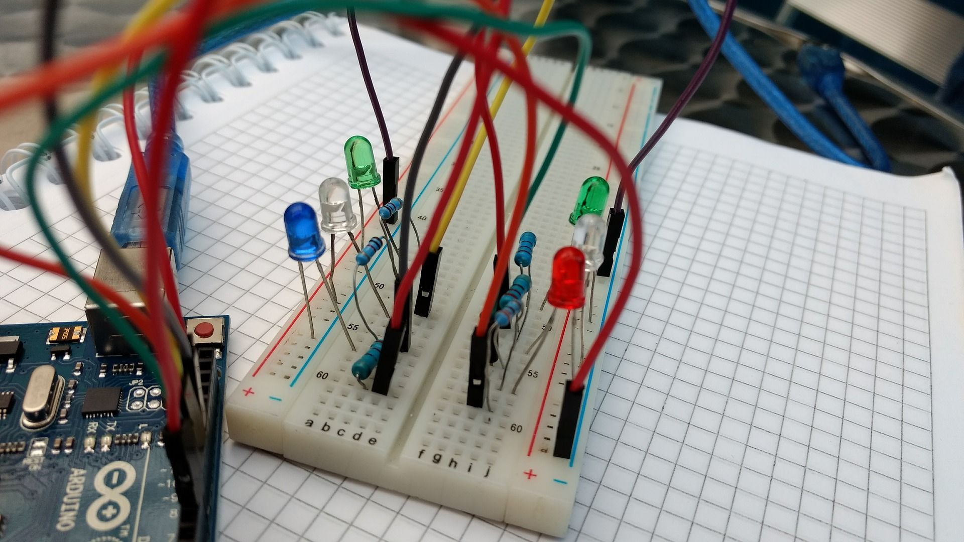
With the availability of tools like easyeda and the possibility to use actual breadboards to plan, explore and test such options beforehand this is only a real problem if there has been no actual planning.And use PIOs build-in unit testing engine if you can, it allows running tests on your local host machine as well as the connected devices.
Which in turn allows you to catch a lot of bugs beforehand.
On that note, if you are not using PIO currently, you really should, it’s integration in Visual Studio Code and Atom makes it really easy to use. And you can extend it feely with VSC or Atom extensions.
Also, if you split your build into parts as well and connect them using cables/sockets/etc. you can swap them out in the future(stepper motor drivers are a great example of this).
Consequences of mistakes
Speaking of doing real damage, when was the last time your software project caused your PC to start burning?
Never, unless you were working in C and put some pointers in some really unfortunate places while simultaneously convincing your os you are really allowed to do this.
Now let us take a look at the hardware side of things. Using the wrong input for a pin? Using the wrong pin in general? Switching a relay at the wrong time? Not switching a relay at the right time?Forgot that a specific component needs to be slowly shut down?
Does not sound great, does it? I for my part killed loads of components over the years and I know that I will kill loads of them in the future.
And while there's not always a good solution to prevent this, only can use careful planning and the addition of fuses in front of expensive and/or important parts to reduce the risk drastically. And if you know that some parts are prone to breaking, give them some sockets and save yourself some soldering time.
Conclusion / TL;DR
There are a lot of things one can do wrong when approaching embedded programming from a pure software programming standpoint.
But here are the things that helped me not produce as much magic smoke as I used to:
- Read your specification
- Read the right specification
- Check connections thoroughly
- Plan your stuff
- Split your hardware into parts
- Don’t hardwire everything
- Prototype and test on breadboard
- Ever heard of fuses?
If you want to support me please use my Amazon affiliate link below:Link
Photo by Harrison Broadbent / Unsplash